
Raspberry Pi3 fan control
Why build a fan control regulator?
I built this project because I was interested in seeing if I understood simple circuits and digital control well enough to make them work in harmony. Turns out ...😄... I do... So, I decide to share what I have made with anyone who cares.
It has always been a persoal goal to achieve software to hardware functionally. i.e. I wanted to personally understand both sides (Software and Hardware) well enough to make the rubber meet the road. I wanted to build a circuit and control it with a computer, without catastrophe. So, I thought, my garage Raspberry Pi3 gets really hot in the summer and I have a random scavanged 12V fan, can I make the Pi control its own temperature. Answer, yes... very easily in fact. What I like most about this project is that the inventor can harness their skill on either side: software or hardware to get the job done. I found writing code is much easier for me than building a very complicated regulatory circuit, so I used this strength to my advantage.
Building the circuit to control a Raspberry Pi3 Fan

Above is the circuit I designed to control fan speed. I simulated its function using EveryCirc which is a really excellent high level software for simulating circuits. The function of this circuit is very simple, effectively you force the RPi3 to act as a switch producing 3.3 volt pulses (far left of the diagram) to pulse a transistor. This transistor opens the flood gates and allows the fan to flow current, it also pulses an LED I added to make it pretty. Importantly, current can only flow through the fan when the NPN transistor (2n2222a) recieves a pulse from the Pi. Simple enough right...
Some considerations I put into this circuit before frying my RPi and/or the transistor:
- What is the maximum current flow capability from collector to emitter for my transistor (2n2222a)?
- What is the maximum acceptable current flow for my RPi3 GPIO pin that I will throw the switch on?
- What is the maximum current flow for my LED, unlike lightbulbs LEDs need to have their current limited via resistors.
All of this information can easily be found by looking up the documentation for each component. The maximum collector to emitter current flow is 600mA, the maximum current flow for all RPi3 GPIO pins (together) is 16 mA, but previous RPI documentation suggests only 3mA is very safe. Given that I'm using a transistor as a power amplifier, I don't need to supply much current from the GPIO pin to fully saturate the transistor. Furthermore, I wouldn't want to, think of the RPi is a controller not a current source (battery, power supply), use it to control current, not supply it. With much deliberation I chose to set a resistor of 2.2k ohm, which at 3.3V using Ohms Law V=IR, would set the current into the base of the 2n2222a as 1.55mA. This is well within the safety margin. Traditional LED current handling is between 15 to 30 mA. I chose 1k ohm which at 9v would allow only 9mA through.
Writing the software to control a Raspberry Pi3 Fan
To be clear the software is really what I was leaning most heavily on in this project, without a brain this project is dead in the water. Lucky for me, thats exactly what the RPi is good at. For those who don't care about my musings on writing a fan regulator and just want to get it done. All the software is available from my github repository, and its really simple to modify to your own purposes.
What were my goals?
- Make a program in a language I know that pulses the 2n2222a transistor in the circuit from a single GPIO pin
- It should be able to run continuously and without my intervention, adjust to core temperature fluctuations and shutoff when I'm done
- Maybe someday use machine learning to optimise the current used?
With these ideas in mind I knew of only one piece of software that could link Python to the RPi GPIO ports. Simply enough, its called RPi.GPIO. After installing via their instructions I found it very easy to use, for examples look here. Obviously, at this point I needed a way to know the temperature of my RPi's core, this can be found by simply typing cat /sys/class/thermal/thermal_zone0/temp . I noticed this file "temp" is updated every few moments and you can use it as a realtime signal of the core temperature. Combining these ideas, I developed a simple function to read the temperature called finding_temp(). If you look at the logic at the bottom of the script you'll see that I first set up the GPIO pin in channels_out. There is no particular reason, I chose pin 37 other than the fact that it was easy to find. After setup, in the absence of keyboard interupt (control-C), the program sleeps for 10 seconds, then checks the temperature of pi, sets the pin to the one you setup in the first step, and initiates the run_fan() function. All this function does is check the temperature the Pi is currently at against a set of variables defined as the variable cutoff (the temperature above which the fans must activate for the first time). If it finds a condition above the cutoff it will fire the fan using increasing length voltage pulses (PWM) as the temperature increases. When the highest temperature cutoff is reached, the fan is run continuously.
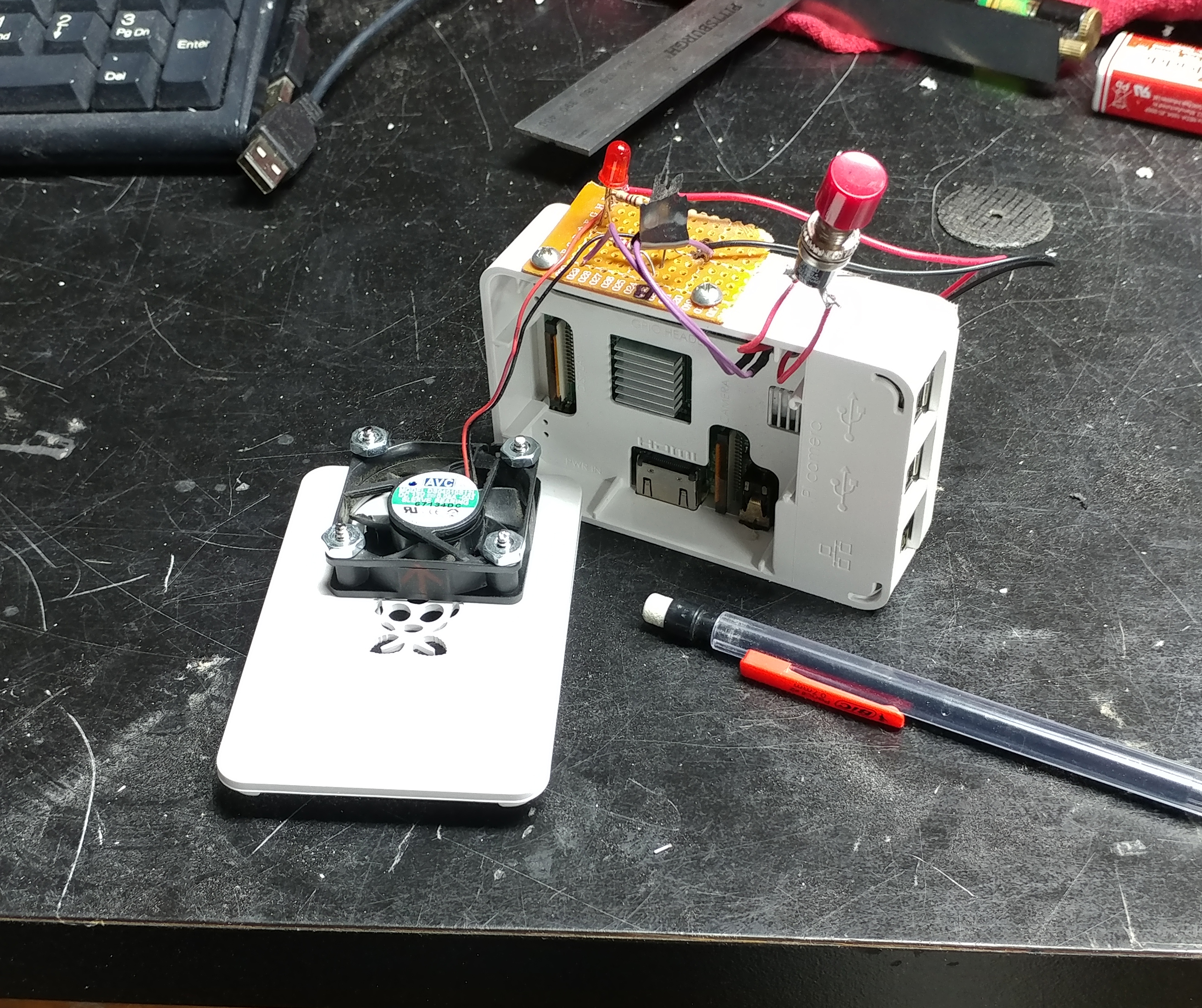
The Final Build
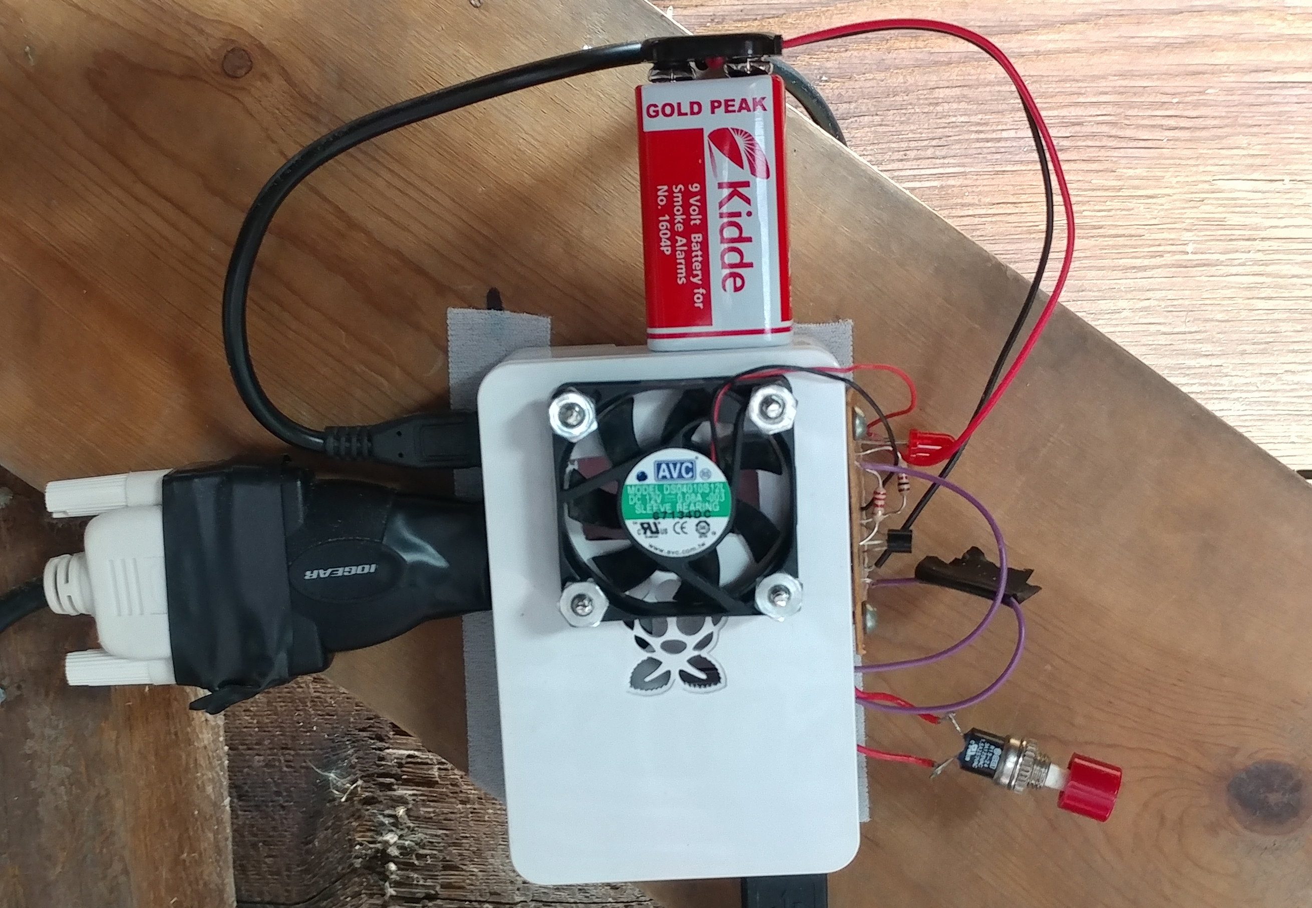
The First Run
Performance:
I have not performed official tests that would force the Pi3 to get super hot, but I can tell you using the Raspian OS and simply pulling websites via WIFI and running a full HD 1080 screen is enough to push my Pi to 80 celcius during a warm Wisconsin day (thats with the heatsink installed on the core chip). My pi resides in the garge as a garage computer. However, using this program my temperatures have never exceeded 65 celcius even with the most load I have put on it to date. So...it works, 15 C cooler is quite acceptable to me for < $5 worth of parts and 1 hour of coding. I'm sure this system could be further optimized. I have the fan pulling hot air out of the Pi, I have yet to try the opposite, pushing outside air in.
Subsequent Testing
Future upgrades:
- I will definitely eventually switch from 9v batterys to a true 9v wall wart, but for now I have a major excess of 9v batterys due to many of my smoke alarms and garage door opener batterys dying simultaneously...
- I plan to eventually use machine learning algorithms from SKlearn to produce a cost function for optimization of the fan energy usage while maintaining low Pi core temperature. Worth it, definitely not in the end... but it will be alot of fun to learn the math and software necessary to make my Pi learn how to save energy!!!