
A Universal DC adapter
A Brief History of Power Distribution using Alternating Current (AC) vs Direct Current (DC)
Alternating Current is an electrical waveform that periodically reverses direction and changes its magnitude continuously with time. This is in contrast to direct current (DC) which flows only in one direction. On the atomic scale we can visualize this as electrons sloshing back and forth a miniscule distance over the copper metal lattice in a wire exactly 60 x per second (Hz). OK... this all seems academically interesting, but not actually useful... right??? AC is the most unanimously used form of electrical power distributed on earth. But why? Why not just use DC to start with? After all, many, if not most electronics we use on a daily basis use DC at some level. The reason for this is historical in nature, in the beginnings of world electrification a great battle known as the War of the Currents ensued between two of the top minds of the electrical world (Nikola Tesla & Thomas Edison). In the end the battle was decidedly won by economic factors. The victory lap was taken with Nikola Tesla's first massive display of the electrification in the 1893 Chicago World's Fair. His polyphase system wowed the world with a display of artificial light brighter than had ever been seen by human eyes. It was enabled by Tesla's induction motor and the newly created AC power transformer. To this day improved versions of those inventions allow smaller wires to carry more power during distribution than DC systems every could. The means is simple, modern power plants use steam turned inductions motors to generate AC and voltage step up transformers to convert low voltage high energy currents --> to high voltage low current. Using high voltage AC means we can pass more current on our distribution wires with less overall heating. Thus, a worldwide grid of electrical energy was born. Mankind had mastered its first fundamental force of nature: electromagnetism.
Power Supply Types
The goal of the powersupply we are producing is to convert AC --> DC, yep like the band...
An Unregulated Power Supply
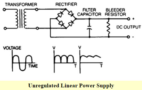
image credit: https://www.elprocus.com/
An unregulated power supply uses a transformer to step down wall voltage (120v @ 60 Hz) to a lower voltage (12v @ 60 Hz). The step down transformer output is fed to system of rectifier diodes that recitify both sides of the AC waveform to a bouncing positive (+) wave. The diodes achieve this by acting as one way valves for current flow, i.e. once current has passed a diode, it cannot return through the same path. Finally, an electrolytic capacitor is used to smooth the bouncing wave to a near flat DC waveform. As might be obvious by the name, unregulated supplies cannot reasonably regulate the voltage at the outputs when conditions change with either the load or the supply. Therefore, for anything requiring more precise voltage regulation they should be avoided.
A Linear Regulated Power Supply
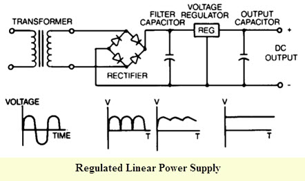
image credit: https://www.elprocus.com/
In a regulated power supply the majority of the above description still applies. One major difference occurs once that the current reaches the regulator IC. The IC uses internal circuitry to vary the input current at whatever level is necessary to maintain the output voltage set by the user. Modern day regulator IC's can reject >75 Db of signal ripple, producing an extremely stable output voltage at the cost of outputting heat at a rate equivalent to the voltage drop across them.
Regulator output examples:
If 12V is applied the leads of the regulator and it is required to maintain a voltage at 6V while flowing 3A through a resistive load. According to Ohm's Law (P=IV) the load will dissipate 18 watts. However, we must not forget about the potential difference still in the circuit. Since we started with 12V and regulated our load voltage at 6V we still have 6V remaining across the linear regulator. Since the load is allowing 3A to flow that means the same 3A current must also flow through the IC. As mentioned 3A * 6V = 18 watts. Even if the load your trying to power can handle 18 watts, it is very unlikely that a non-heatsinked regulator could dissipate it before destruction. In the real world a mistake like that would likely lead to something like this in a matter of msec :
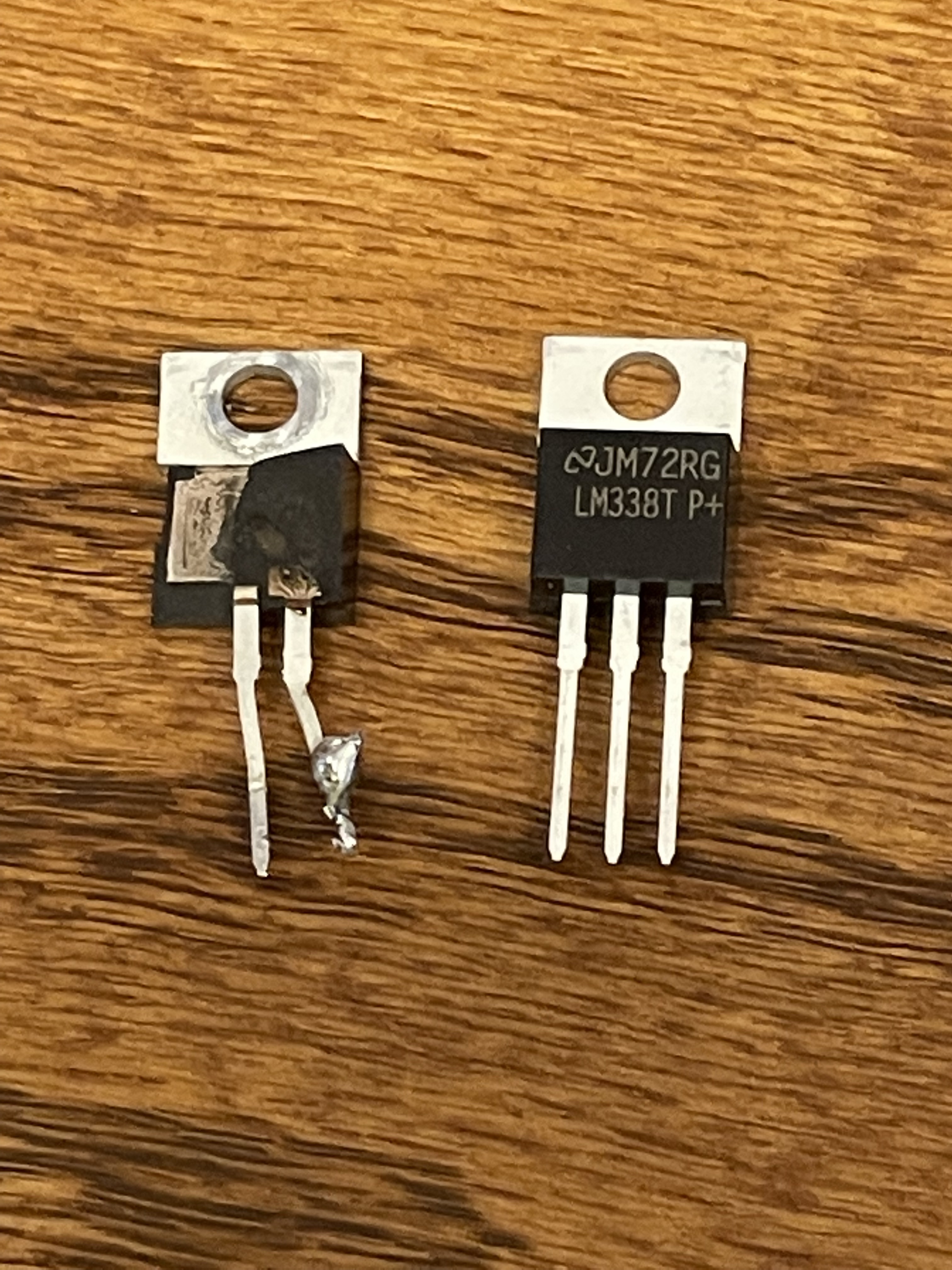
On the left is the remainder of a linear regulator IC designed to handle 5A @ 24V. Moments before it exploded an accidental dead short occured at the output terminals. Needless to say, protection from mistakes like this are essential, but hindsight is 20/20.
A Dual Rail Linear Power Supply with Short Circuit Protection
Custom Built Overcurrent Protection Circuit
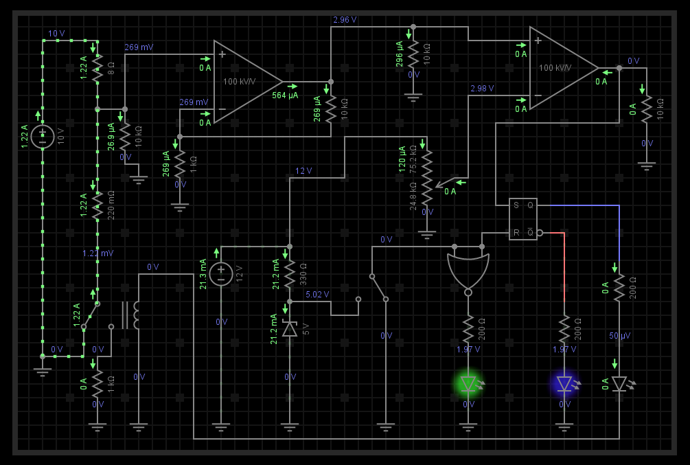
EveryCircuit Simulation of this custom circuit
Description of Operation
This is a functional overcurrent protection circuit. It measures the voltage drop across the 220 mOhm resistor on the far left supply. That voltage is boosted and compared against a reference voltage in the second opamp (comparator mode) and an SR latch is used to latch the overcurrent result.
If the output of the first opamp is lower than the inverting input (-) voltage the output of the second opamp is low, otherwise the output goes high.
The output of the second opamp is fed to an SR latch (2 NOR gates). When the opamp output and the reset switch are low the output Q is low and the relay is off (i.e. the circuit operates normally).
When the opamp goes high (due to sensing an overcurrent event across the 0.22 ohm resistor) Q latches, the red LED turns on and the circuit deactivates nearly instantly protecting your supply. You can simulate overcurrent by reducing the 8 ohm resistor resistance.
To reset the system properly, flip the switch to high and back to low. This resets the latch (and green LED protected indicator). Note the circuit will only continue operating again when you increase resistance of the primary load (>= 8 ohm).
Power supply in shutdown state (red led active)
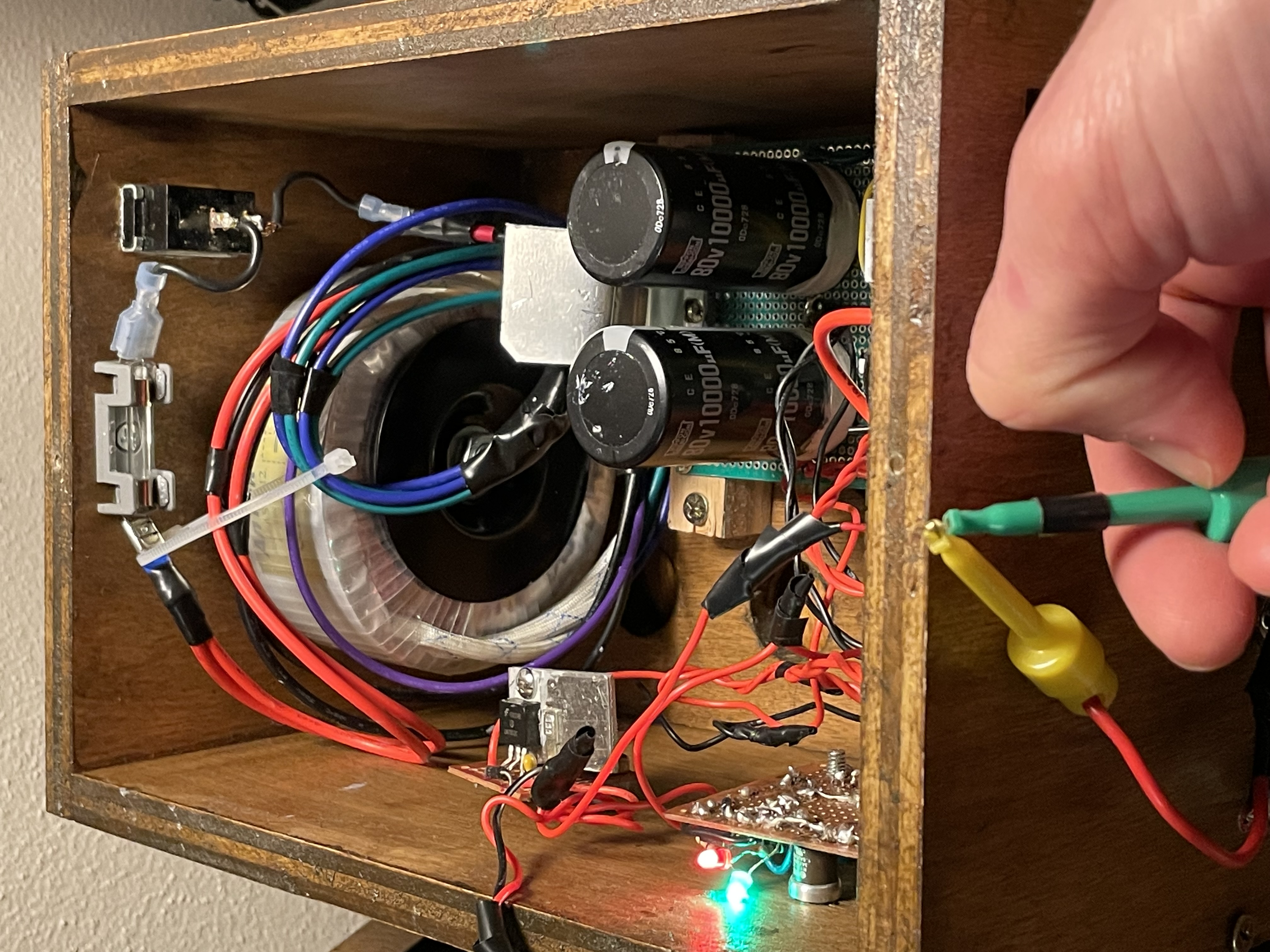
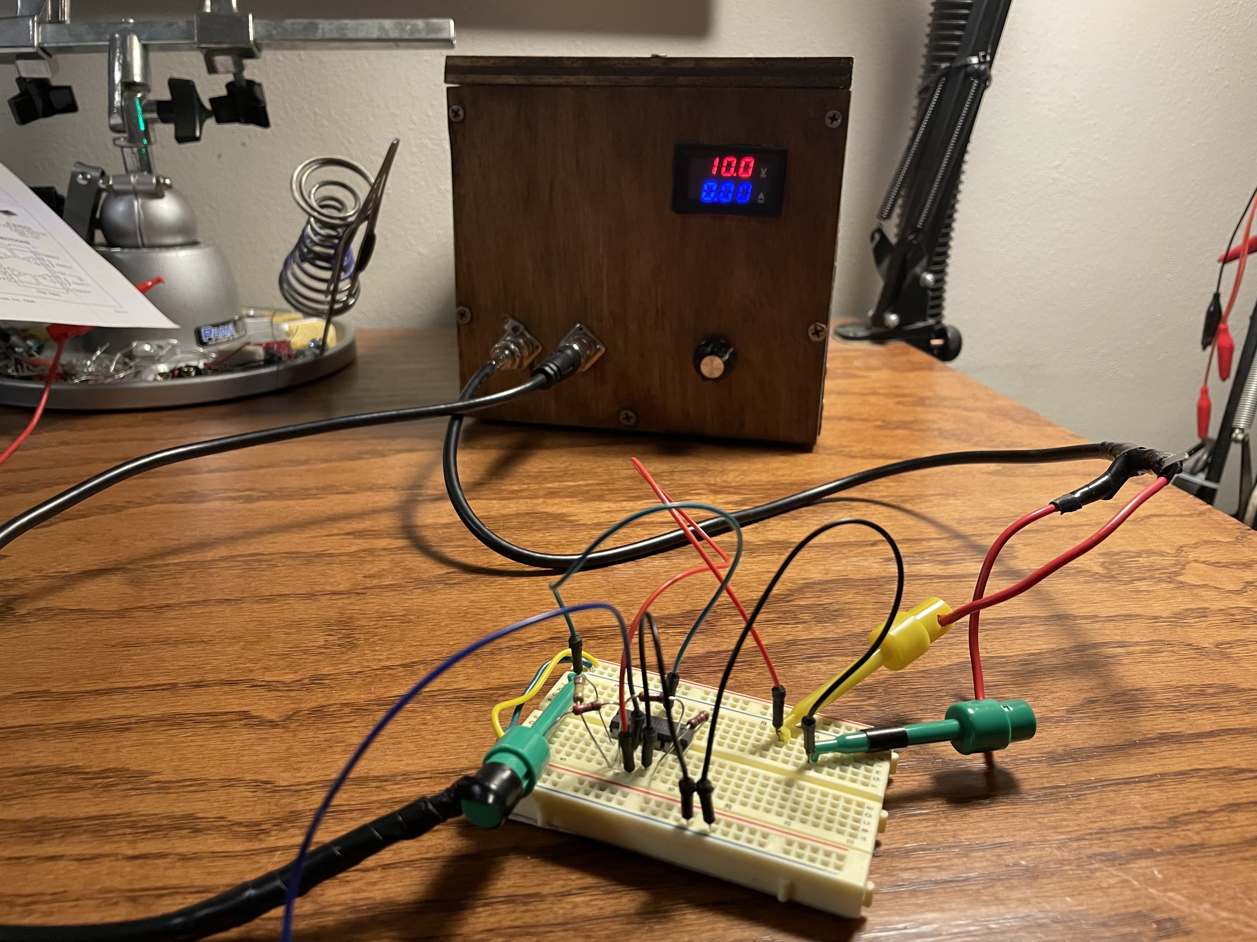
My system is hardwired to allow no more than 2A @ 16VDC. If the resistance of load drops below a threshold that higher than 2A would flow the protection circuit activates and immediately shuts off the supply. It can only be reactivated through the reset switch.
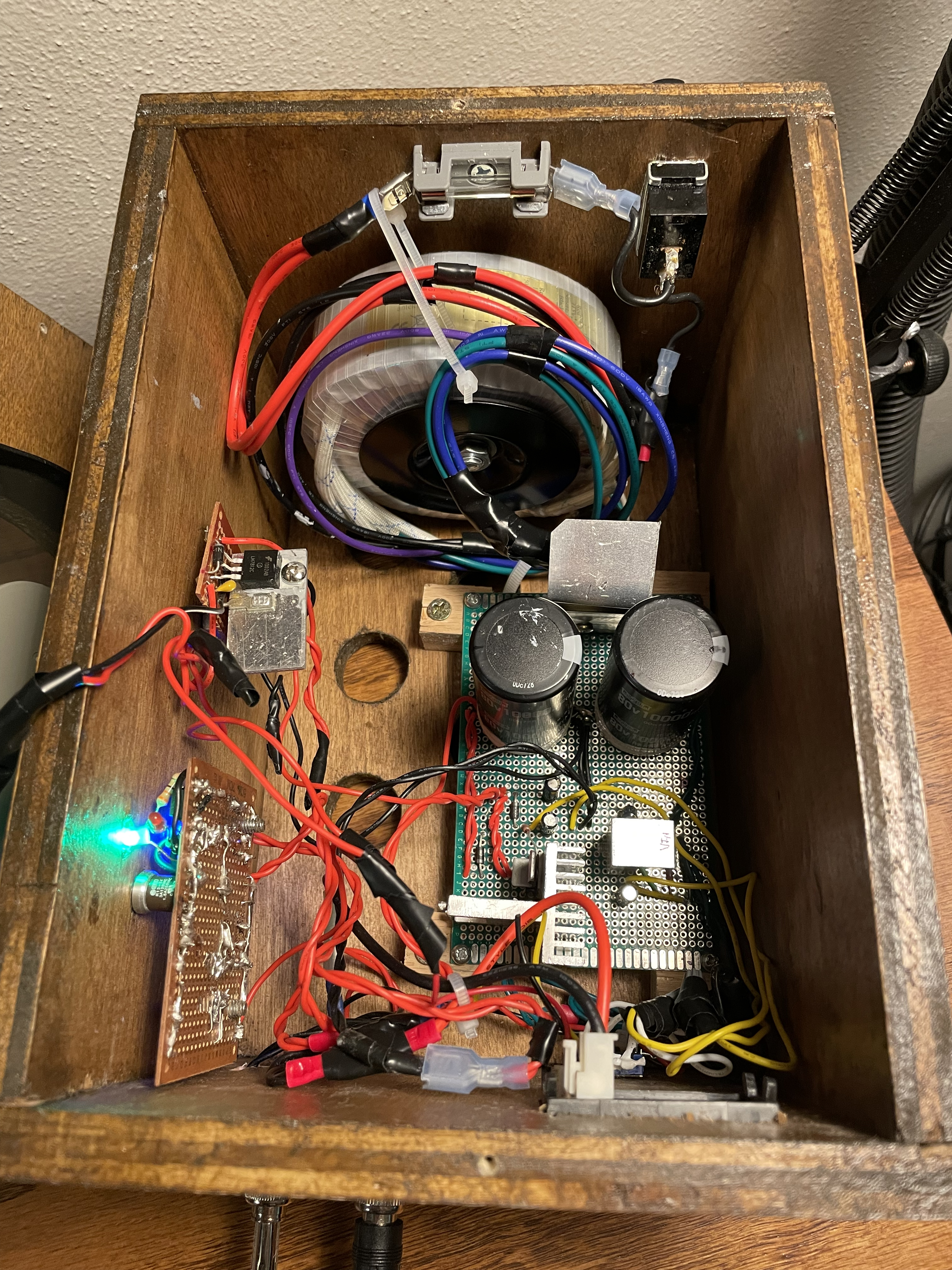
Power supply in active passing current state (blue led active)
Enough nonsense, what can you use it for?
We have just built the universal DC adapter :). Anything that runs on voltages below 16V and requires < 2A current can be powered by this circuit. This includes: computers, motors, arduinos, fans, whatever you can come up with that takes DC electricity. The inherent safety added by the protection circuit makes this a perfect power system for testing parts and fixing other electrical systems.
Why build the supply with +/- rails?
Operational Amplifiers (opamps)
Having a supply with + & - voltage rail allows the user to amplify analog signals like music or sensor data with massive signal gain. One way to do this is to use an opamp.
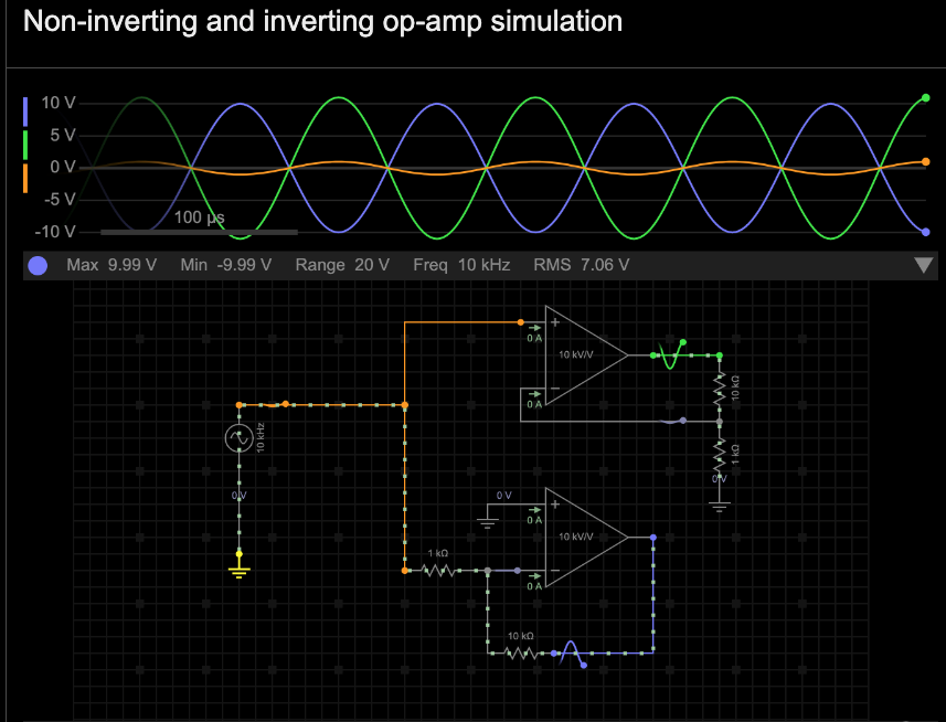
View this non-inverting and inverting op-amp simulation. Using the circuit configuration shown allows both amplification and inversion of any analog input signal within that opamps range. The results in real life are nothing short of astounding...
100x signal gain using using a non-inverting amplifier w/negative feedback
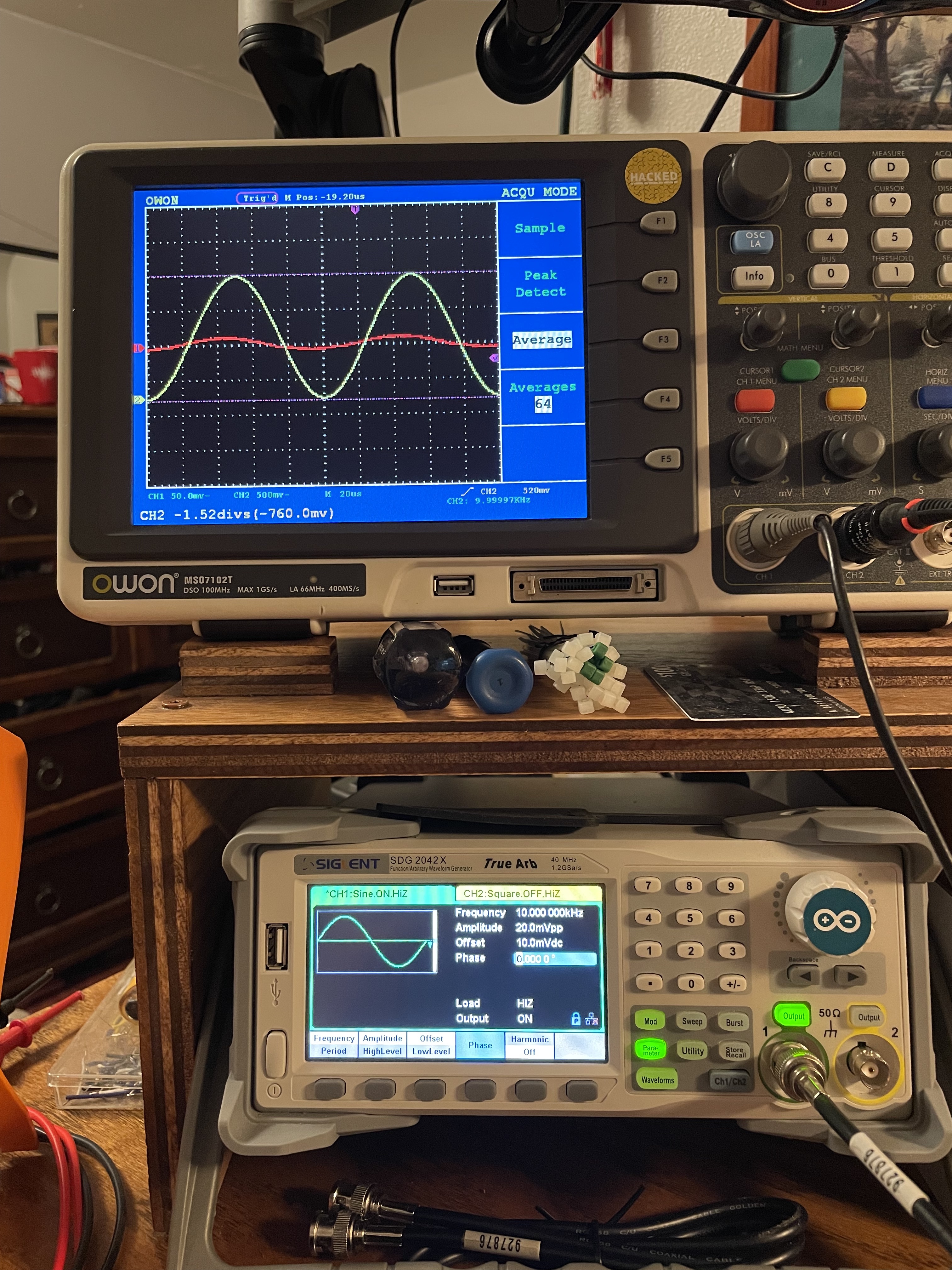
Input Signal (20 mVpp)
NonInverted Output Signal (1.8 Vpp)
Using the linear power supply with +/- 10V rails fed to the opamp we can amplify the sine wave (20 mVpp) input to nearly 2 Vpp (~100x gain) with near perfect accuracy using a Motorolla MC33174. In order to amplify the signal without clipping the waveform, the range of the rails must be larger than the highest amplified output on both edges. In this case, we were aiming for 100x amplification and nearly achieved it.
Waveform Inversion & 100x signal gain using an inverting amplifier
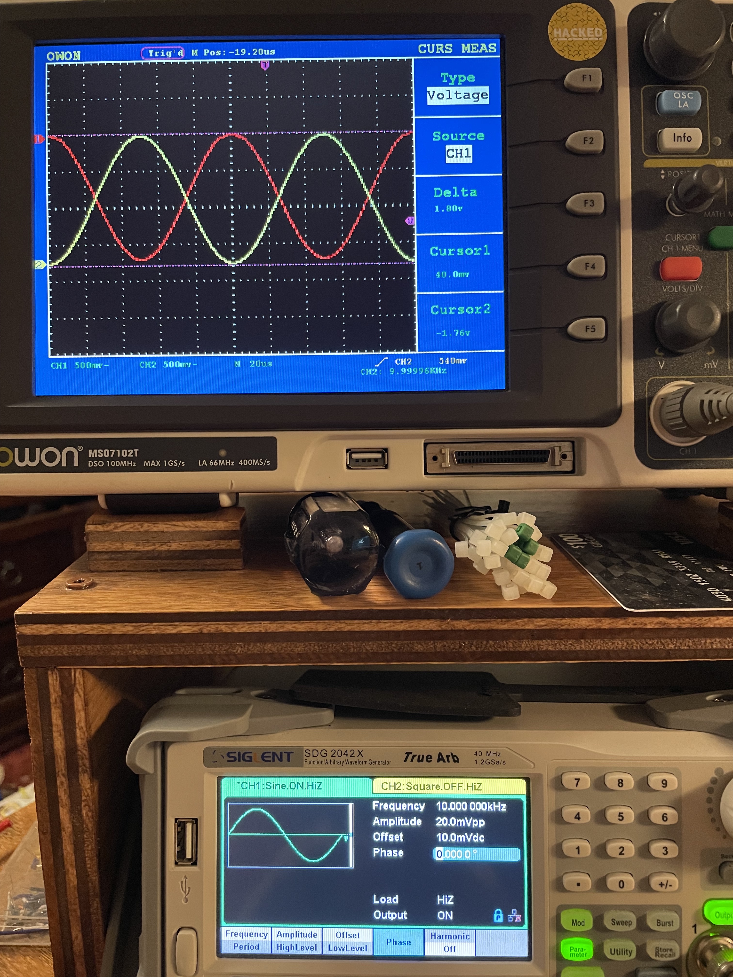
NonInverted Output Signal (1.8 Vpp)
Inverted Output Signal (1.8 Vpp)
Amplifying live audio from Language by: Porter Robinson
Audio Input Signal (100 mVpp scale)
Voltage Amplified Output Signal (1 Vpp scale)